

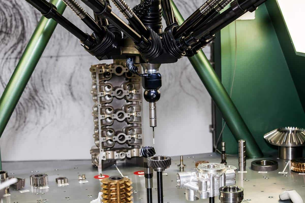
Design engineers and manufacturers use coordinate metrology to precisely measure the features of machine parts. By mapping coordinates onto a given workpiece, coordinate measuring machines (CMMs) can compare parts along a production line, or even predict whether a prototype is up to scratch.
The French theorist René Descartes developed coordinate mapping in the 17th century, and the study of maps, cartography, takes its name from his. From this original plotting system, modern machinists measure and map cutting-edge parts with finely tuned CMMs. As everyone is familiar with some form of coordinates from street maps to games like Chess and Battleships, it’s easy to find examples for even the most complex principles in coordinate metrology.
How do Coordinate Measuring Machines Work in Coordinate Metrology?
Like a fingertip scanning a map to find a landmark, CMMs use a sensitive probe to places a workpiece feature at a coordinated location. The machines operate on three axes: X, Y and Z. As you look at the machine, the X axis maps from side-to-side, the Y axis maps forwards and backwards, and the Z maps up and down. By giving a feature a reading on these three axes, CMMs assign them a unique location. Crucially, this location is relative to all others on the workpiece. They can, therefore compare features and predict relationships between them.
CMMs use three different types of probe: the solid probe, most closely comparable to the human finger, the touch-trigger probe, and the laser probe. Touch-trigger probes use pressure sensors to automate coordinate measurement. They measure information whenever the tip makes contact with a workpiece. Laser probes, on the other hand, measure coordinate features by emitting and receiving light.
All CMMs combine two systems of data to make judgements and predictions about the workpiece they measure. They combine machine coordinate systems and part coordinate systems.
Machine coordinate systems refer to the X, Y and Z grid of the CMM itself. Part coordinate systems introduce the shapes of the workpiece to be measured. Put simply, the machine coordinate systems are the large square grids of a map, and the parts coordinate systems are the streets and buildings that criss-cross through them.
In comparing the two, to learn about a workpiece, a CMM conducts a process called alignment, a central tenet of coordinate metrology. In order to unpack the details of alignment in coordinate metrology, it’s important to learn a few key terms used by engineers in the industry.
Alignment in Coordinate Metrology
Alignment is the combination of machine and part coordinate systems for measurement and comparison. As a process, alignment predates the digitisation and modernisation of CMMs and coordinate metrology. Before the powerful algorithms and calibrated software common in today’s CMMs, operators would simply align machine parts parallel to a CMM’s axes. They would level their workpieces by eye, or at best with some form of spirit level.
Not only is this method time-consuming and often inaccurate, it suffers further in the case of domed, curved, or bevelled workpieces. Such gradients require recalibration and adjustment to get accurate measurements.
Modern CMMs carry out these adjustments automatically with their alignment routine software. This process is best understood through a return to the map analogy, as both navigation and coordinate metrology rely heavily on coordinates.
For CMMs, alignment is like orientating yourself with your map and both facing the same direction to understand your environment. To use a more modern example, it is like hitting the recentre button on a satnav. The machine and part coordinate systems line up, and from there, an operator can measure and compare each datum on the workpiece.
A Workpiece Datum
In coordinate metrology, the word datum takes on a specific and useful meaning. “Datum” is actually the Latin singular of the word “data”: technically, we should say one datum, two data.
For a CMM and its operator, a datum, or piece of information, refers to a coordinate on a workpiece. It also serves to highlight the feature in that coordinate. A datum could refer to a hole, protrusion, or panel on a part.
On a conventional street map, a datum could be a particular house. In the game Battleships, it could be a battleship or a point in the water. CMMs compare separate datums on a workpiece to assess their properties and predict their relationships. When comparing datums, they often use a process called translation.
Translation
Translation, in coordinate metrology, becomes necessary to work out the relationship between workpiece datums. Essentially, translation is the shift from locating a datum in terms of a grid, to locating it in terms of other datums.
On a street map, you find yourself by running your finger along the numbers and letters of the grid. When you need to plan a route, you translate your starting point to yourself, then work out where you need to go from there. Similarly, in Battleships, when you get your first hit, you translate your guesses from the hit, not just from the whole ocean.
Using coordinate translation, CMMs determine the route, and therefore the distance, between datums. When the two datums are already parallel with one another, this comparison becomes as easy as finding a parallel street in a grid-based city.
Workpieces historically used simple machining techniques to create parts, so this was generally the case. However, modern coordinate metrologists determine shapes through seven geometric elements to define a part: point, line, plane, circle, cylinder, cone, sphere. With the dawn of 3D printing, parts can have free-flowing shapes with datums of all angles. To translate between non-aligned datums, CMMs use rotation.
Rotation
This fairly self-explanatory concept involves rotating datum information, so it lines up with another datum. Rotation allows a CMM to determine distance and relationship, and compare the qualities of different datums. While the process sounds simple, a CMM performs complex translation and rotation calculations to accomplish this feat.
Rotation and translation provide the link between measurement and prediction in coordinate metrology. The extrapolation of one datum onto another helps determine their existing relationship, as well as predicting their future interactions, through a process called projection.
Projection
Projection, or the reproduction on one datum onto another, proves essential for predicting the behaviour of a machine with moving parts. The compatibility of these relationships often separates efficiency from error, particularly in complex machines like clocks or cars. If a clock’s cogs fail to mesh snugly, the whole system falls apart. Although combustion engines rely on explosions, the relationships between pistons, chambers and fuel separate the useful explosions from the dangerous.
Projection helps mediate these relationships in advance, with constructed features. CMMs construct features like centrelines, intersection angles and symmetry based on projected datum sizes and trajectories. Essentially, CMMs can project the angles of a square peg onto the opening of a round hole, to predict that the two will not mix. They use further checks, called volumetric compensation, to ensure their results are as accurate as possible.
Volumetric Compensation
Although CMMs are intelligent and sophisticated machines, their software acknowledges possible errors in measurement to improve their result. Volumetric compensation is the process of accounting for such errors, including the roll and pitch of the measurement process or possible skidding and vibrations on the workpiece surface itself.
With volumetric compensation, the CMM computer’s algorithms map these errors, correcting the vast majority wherever possible. Doing so saves manufacturer and consumer time and money, while also improving the effectiveness of the measured workpiece by ensuring all the datums are correct.
Coordinate metrology puts centuries-old principles through modern machines to measure, compare and predict their qualities. These calculations seem complicated and convoluted at times, but coordinate measuring machines make the job logical and reliable. In doing so, they maintain high standards on production lines and prove which prototypes will be the machines of the future.
Jeff Eley is the founder and managing director of Eley Metrology, a leading company in the precision measurement industry. With decades of experience in metrology, Jeff has established himself as a respected figure in the field. Under his leadership, Eley Metrology has become renowned for its expertise in coordinate measuring machines (CMMs), digital height gauges, and granite metrology products. Jeff’s vision has driven the company to develop innovative solutions, including custom-designed CMMs and the flagship long-bore measurement machine (LBM). His commitment to excellence and customer-centric approach has positioned Eley Metrology as a trusted provider of high-precision measurement tools and services for industries such as aerospace, automotive, and manufacturing.